
EC UL Cooling System Design
Brief
Design the cooling system of the Electron Cyclotron Upper Launcher subsystem of the ITER nuclear fusion reactor and validate it according to the applicable design codes (ASME B31.3), taking into account all loading conditions associated with normal operation and predictable accidental and incidental scenarios.
Project challenge
- Design of Pressure Equipment used in a nuclear installation, in accordance with European Directives and French regulations.
- Heterogeneity of loading conditions, to be considered individually and in combination, according to the reference scenarios.
- The need for MultiPhysics simulations for thermo-structural analysis of the Port-plug under applicable thermal, mechanical and electromagnetic loads.
- Testing the structural integrity of system components by applying applicable building codes.
Solution
- The engineering team completed the hydraulic design of the cooling circuit and the corresponding Piping and Instrumentation Diagram and Process Flow Diagram were drawn up.
- The detailed design of the portion of the circuit that implements the first refrigerant confinement was completed (3D model and drawings).
- Fluid-dynamic simulations of the CFD refrigerant flow within the circuit were developed in order to evaluate pressure losses and velocity distributions.
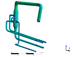
- Thermo-structural simulations were developed using finite element models (FEMs) of the portion of the circuit that realises the first confinement of the coolant subjected to seismic dynamic loads.
- A 1D hydraulic model of the cooling circuit was developed in order to verify the adequacy of the proposed architecture with respect to the applicable requirements (available flow rate, inlet temperature and maximum outlet temperature, maximum overall pressure drop, minimum flow rate to be supplied to each component, maximum pressure drop introduced by each component).
- The results of the analyses (stress and displacement distributions) were used to verify the structural integrity of the circuit components, using the rules defined by the applicable construction codes.
CFD: Computational fluid dynamics
FEM: Finite Element Method
Execution phases
Hydraulic design of the cooling circuit.
Completion of the detailed design of the portion of the circuit that implements the first refrigerant confinement (3D model and drawings).
Creation of the numerical model for FEM and CFD analyses: generation of the calculation mesh, imposition of constraint and load conditions.
Execution of the analyses.
Development of the hydraulic model of the cooling circuit.
Verification of the structural integrity of the components (stress assessment) by applying the construction code rules.
Achieved results
The design was carried out using CATIA V5 and ENOVIA V6 (3D model and drawings).
Numerical simulations were performed using ANSYS Workbench 18.2 and ANSYS Mechanical 18.2.
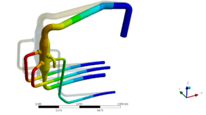
First mode of vibration
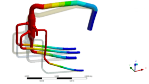
Second mode of vibration
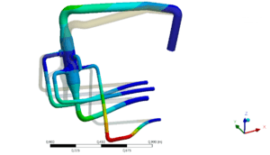
Third mode of vibration
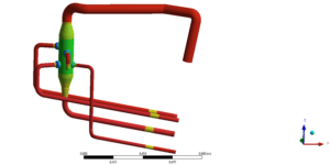
Steady-State thermal analyses
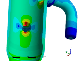
Static structural analyses